
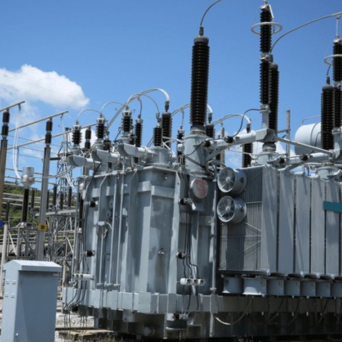
Transformer impedance is not an isolated nameplate value. Change it and the downstream fault level changes; voltage drop changes; the feasibility of parallel operation may change as well. It should come from the system study rather than a copied specification.
A simple way to see the trade-off
This is a first-pass transformer contribution, not a replacement for a complete short-circuit study.
For a 10 MVA transformer, 6% impedance corresponds to roughly 167 MVA at its terminals before upstream details are included. At 8%, the same first-pass value falls to about 125 MVA. Higher impedance reduces fault current, but also produces more voltage drop for a given load current and power factor.
Three checks should be made together
- Switchgear duty.
Calculate prospective current at every bus and compare it with making, breaking and short-time withstand ratings.
- Voltage performance.
Review normal regulation, large motor starting, transformer energisation and the weakest operating configuration.
- Parallel loading.
Confirm ratio, vector group, tap position and impedance magnitude; examine X/R relationship where load sharing is important.
Do not negotiate impedance only after quotations arrive
A manufacturer may propose a different impedance to suit an established design platform or short-circuit requirement. That deviation can be acceptable, but it needs to return to the network model. Check switchgear, protection sensitivity, voltage regulation and losses before accepting it.
Practical rule: state both the required impedance and permitted tolerance, then identify the study or operating limit that justified them.