
1.2 GWp Solar Grid Connection
Solar collector system · main step-up substation · 400 kV grid interface
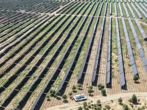
In northern Arad County, a publicly disclosed 1.2 GWp photovoltaic project is planned as a phased development. Its electrical system has to collect inverter output across a wide site and deliver it to an existing 400 kV transmission line through dedicated substations and underground high-voltage cable.
Follow the power path
- 01
Inverter stations
Convert the array’s DC output and establish the operating envelope seen by the medium-voltage equipment.
- 02
MV collection network
Combines repeated generation blocks while controlling cable loading, voltage rise and fault contribution.
- 03
Main step-up substation
Transforms the collected output and brings protection, metering and plant control into one coordinated interface.
- 04
400 kV interconnection
Exports power through a dedicated interconnection substation and approximately 3.5 km of underground high-voltage cable.
The transformer is sized by studies, not DC megawatts
The solar field’s 1.2 GWp DC figure cannot be copied into a transformer schedule. The AC export limit, inverter capability curve, reactive-power obligation, ambient conditions, curtailment strategy and planned construction phases determine how many main transformers are required and how each unit is rated.
Phased energisation deserves particular attention. An early phase may operate with fewer collector feeders and a different reactive-power balance than the completed plant. Protection settings, cooling stages and auxiliary supplies need a defined configuration for every commissioning step—not only for final build-out.
| Grid-study output | Equipment decision it informs |
|---|---|
| Maximum and minimum voltage cases | Tap range, OLTC control and insulation coordination |
| Reactive-power requirement | Transformer MVA margin and compensation equipment |
| Harmonic assessment | Loss evaluation, thermal design and filtering interfaces |
| Fault levels and clearing times | Winding withstand, switchgear rating and protection scheme |
EPC coordination starts at the interfaces
A complete supply plan should freeze the inverter-to-transformer voltage, collector feeder count, cable entries, control protocol, grid-code test responsibilities and energisation sequence before long-lead equipment is released. Civil, transport and drainage information must advance at the same time: the published project includes substations, access roads, control systems and underground transmission infrastructure as one connected facility.